BBC2DVI Guide
Use |
↖ |
BBC2DVI connects the Acorn BBC (model B, B+, Master) and Electron to modern displays.
It does not produce any of the visual artifacts that other solutions do. It does not use an arbitrary or near-enough sample rate (resulting in inaccurate, drifting colours, loss of sharpness, pixels shifting, and frames tearing, skipping or repeating). It uses advanced techniques to sample every incoming pixel exactly once, all the time. As good as it gets.
Your computer will output either interlaced or non-interlaced video. Through BBC2DVI, this will be displayed as either '576i' (720 x 576 pixels interlaced) or '576p' (720 x 576 pixels progressive) :
| BBC2DVI ↓ | MODE 0-6 interlaced | MODE 0-6 non-interlaced | MODE 7 (always interlaced) | but if PLAY_TRANSPOSED = 1 |
|---|---|---|---|---|
| 10M02 1.00 / 1.01 | 576i | 576p | 576i | always 576p |
| 10M02 1.02 | 576p | 576p | 576i | exchange 576i and 576p |
| 10M40 / 10M50 1.02 | 576p | 576p | 576p | always 576i |
If you are unsure about what BBC2DVI you have : the biggest black chip is marked '10M02', '10M40' or '10M50', and five or six groups appearing on the overlay implies 1.00 / 1.01 or 1.02 respectively.
An Electron can only produce interlaced output. A BBC can produce non-interlaced output in screen modes other than 7 (by entering e.g. '*TV 0,1', which can be made to 'stick' on a BBC Master by e.g. '*Configure TV 0,1').
BBC2DVI's output can be tweaked by changing the values of its 'configuration variables'. This can be done by means of :
The configuration variables are :
TUNE_BBC, TUNE_ELK and TUNE_TTX are described in the 'Installation' section of this manual.
SHOW_INFORMATION, when 1, enables the overlay, which displays several dynamic and fixed values, on one line. The line is shown at both the top and bottom of the screen. From left to right, the value groups are : output flags (BBC2DVI 1.02 only), input flags, jitter level, 9-way DIP switch values, 4-way DIP switch values, unique ID. The output flags are : 576i (1) or 576p (0) output, de-interlacer on (1) or off (0) (BBC2DVI 10M40 / 10M50 only). The input flags are : BBC (1) / Electron (0) detect, pixel (1) or teletext (0) mode, interlaced (1) or non-interlaced (0) input. The jitter level is determined once every field, and is displayed in hexadecimal. The 9-way DIP switch values are : TUNE_BBC, TUNE_ELK, TUNE_TTX. The 4-way DIP switch values are : SHOW_INFORMATION, DISABLE_INTERFACE, PLAY_TRANSPOSED, JITTER_FILTER. The unique ID, as implied, uniquely identifies your particular BBC2DVI.
DISABLE_INTERFACE, when 1, completely disables the soft interface. This can resolve cases where the soft interface is falsely triggered by some of your computer activity. It is extremely unlikely that you will ever need this, but it's there.
PLAY_TRANSPOSED, when 1, changes the '576i or 576p' sense (see table above). This may be useful for testing, or to stop the display from 'juddering' (as some do if they do not fully support '576i').
JITTER_FILTER, when 1, will replace any suspect pixel samples with a 'half bright' pixel. It can help when your BBC produces very jittery video in screen mode 7.
PALETTE allows the eight primary colours that are normally displayed to be replaced by any other colour (out of 16 million). There are actually four of these 8 x 24-bit RGB palettes (one for every pixel in any block of 2 x 2), which allows for many patterning effects.
Refer to 'The DIP switches' or 'The soft interface' for information on how to change the configuration variables.
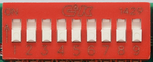
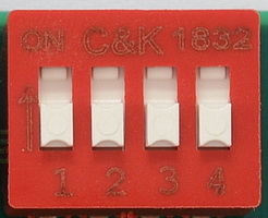
The 9-way and 4-way DIP switches look like this :
All DIP switches can be moved to one of two sides : 'ON' (as marked on the DIP switch, i.e. nearest the PCB edge), or 'OFF' (other side). All DIP switches also have a number (as marked on the DIP switch).
DIP switches, either on their own or in a group, encode the value of a configuration variable. On their own, they encode a value of either 1 (the switch is 'ON') or 0 (the switch is 'OFF'). In a group, they each encode one binary bit of a value (as bit 0, 1 or 2 they add 1, 2 or 4 to the value respectively (switch is 'ON') or 0 (switch is 'OFF')). For example, if the switches for bits 0 and 2 are 'ON' and the one for bit 1 is 'OFF', the value is 5.
The 9-way DIP switch maps to the following configuration variables :
| Variable ↓ | Switch 1 | Switch 2 | Switch 3 | Switch 4 | Switch 5 | Switch 6 | Switch 7 | Switch 8 | Switch 9 |
|---|---|---|---|---|---|---|---|---|---|
| TUNE_BBC | bit 2 | bit 1 | bit 0 | ||||||
| TUNE_ELK | bit 2 | bit 1 | bit 0 | ||||||
| TUNE_TTX | bit 2 | bit 1 | bit 0 |
The 4-way DIP switch maps to the following configuration variables :
| Variable ↓ | Switch 1 | Switch 2 | Switch 3 | Switch 4 |
|---|---|---|---|---|
| SHOW_INFORMATION | bit 0 | |||
| DISABLE_INTERFACE | bit 0 | |||
| PLAY_TRANSPOSED | bit 0 | |||
| JITTER_FILTER | bit 0 |
The soft interface offers a unique configuration variable (PALETTE), and allows all other configuration variables (whose default values are determined by the DIP switches) to be overridden.
The soft interface is used by sending it commands via the display. Command bits are encoded by pixel colours (black means 0, any other colour means 1), and commands are detected by being surrounded by magic values. One command each (consisting of a 64-bit magic value) enables and disables configuration writes. One command each (consisting of a 32-bit magic value and a 32-bit payload) writes 'what' (akin to a register number) and 'data' (akin to a register value). One 'what' can be followed by many 'data's. All commands are received in big-endian order (leftmost pixel is the MSB). Only 2 colour, 16 MHz pixel rate screen modes (i.e. 0 and 3) can be used.
The commands are :
| Command | Encoding |
|---|---|
| Enable writes | 0x5BCDD0AA6F803F2D |
| Write 'what' | 0x3E6D9DE1xxxxxxxx |
| Write 'data' | 0x35A9249Bxxxxxxxx |
| Disable writes | 0x14E1AE57346470B3 |
The 'what's are :
| What | Description |
|---|---|
| 0 | Flags/fields |
| 1 | Palette entry |
The data for 'Flags/fields' is :
| bit 31-29 | bit 28-16 | bit 15-13 | bit 12-0 |
|---|---|---|---|
| - | AND mask | - | XOR mask |
where both masks apply to configuration variables :
| bit 12-10 | bit 9-7 | bit 6-4 | bit 3 | bit 2 | bit 1 | bit 0 |
|---|---|---|---|---|---|---|
| TUNE_BBC | TUNE_ELK | TUNE_TTX | SHOW_INFORMATION | DISABLE_INTERFACE | PLAY_TRANSPOSED | JITTER_FILTER |
The new value is the DIP switch value ANDed and then XORed by the respective masks. This gives you a choice of : 'DIP switch unchanged' (AND 1, XOR 0, the default), 'toggled DIP switch' (AND 1, XOR 1), 'force to 0' (AND 0, XOR 0) or 'force to 1' (AND 0, XOR 1).
The data for 'Palette entry' is :
| bit 31 | bit 30 | bit 29 | bit 28 | bit 27 | bit 26-24 | bit 23-16 | bit 15-8 | bit 7-0 |
|---|---|---|---|---|---|---|---|---|
| write enable 3 | write enable 2 | write enable 1 | write enable 0 | - | primary colour | red | green | blue |
Palette number 0, 1, 2 or 3 is updated if the corresponding write enable is 1 (any combination of enables is valid). Primary colour numbers are as on the BBC and Electron (0 is black, 1 is red, etc.). Palettes 0 and 1 apply to the same pixel row, 2 and 3 to another. Palettes 0 and 2 apply to the same pixel column, 1 and 3 to another. For example, setting palettes 0 and 1 to regular colours, but 2 and 3 to all black, would create a 'CRT effect' (every other line black). The exact alignment of the palettes with the framebuffer content is unspecified (it depends on too many variables).