GoMMC Guide
Installation |
↖ |
GoMMC can be installed in a BBC model B, BBC Master, BBC B+ or Electron.
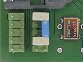
1) Take note of GoMMC's 10-pin configuration header (the one with the grey and blue jumpers on it), in the following picture :
Its pins (in the orientation shown in the picture) are numbered :
| 9 | 10 |
| 7 | 8 |
| 5 | 6 |
| 3 | 4 |
| 1 | 2 |
So, in this example, there's a grey jumper on 3+4 and 9+10, and a blue one on 6+8 (note that your jumpers may be a different colour). The positions of the jumpers will differ depending on, among other things, what type of machine GoMMC is installed in.
2) Take note of the 'extras' that were supplied with your GoMMC :
3) Now skip ahead to BBC model B installation, BBC Master installation, BBC B+ installation or Electron installation, depending on which machine you have.
1) Establish orientation inside the machine. Looking at the components, with the keyboard facing you, take note of 'north', 'south', 'east' and 'west' (e.g. the power supply is now 'north-west').
2) Take note of the ROM sockets that are available for installation. They are :
| IC number | ROM number |
|---|---|
| 101 | 15 |
| 100 | 14 |
| 88 | 13 |
| 52 | 12 |
They are located below the keyboard, on the 'east' side of the machine. The IC numbers are hard to read, because they're in a small gap between the sockets. So, for your reference, from the 'east' side of the machine, going 'west', they are 101, 100, 88 and 52. The BASIC ROM is usually ROM number 12, but note that you can move it to any other socket, if need be.
3) About the 'socket-to-wire-to-jumper' adapter (henceforth called 'the adapter') that came with your GoMMC. Only with the adapter installed, GoMMC can use the 'free ROM bank on GoMMC' to auto-load patched filing systems (refer to other parts of this manual for details). If you have sideways RAM banks in your machine that GoMMC can use instead, or you're going to have one or more PROMs with a particular patched filing system permanently installed in your machine, installing the adapter is not really necessary.
4) Choose one of the following recommended configuration options :
| Option | GoMMC ROM | Adapter ROM | Comment |
|---|---|---|---|
| A | 15 | - | Free ROM bank unusable |
| B | 15 | 12 | GoMMC can control 15 |
| C | 14 | 15 | GoMMC can't control 15 |
There are other options, but these will either short the adapter wire against the GoMMC PCB, or weaken GoMMC's control over other ROM sockets (the higher the ROM number of GoMMC, the more control it has).
You should now have something resembling this picture :

Ready.
You should now have something resembling this picture :

Note and check the correct orientation of the adapter socket.
Ready.
1) Establish orientation inside the machine. Looking at the components, with the keyboard facing you, take note of 'north', 'south', 'east' and 'west' (e.g. the power supply is now 'north-west').
2) Take note of the ROM sockets that are available for installation. They are :
| IC number | ROM number |
|---|---|
| 37 | 6+7 |
| 27 | 8 |
| 41 | 4+5 |
They are located just 'south' of the MOS ROM (IC24), on the 'east' side of the machine. The IC numbers are hard to read, because they're in a small gap between the sockets. So, for your reference, from the MOS ROM, going 'south', they are 37, 27 and 41.
3) About the plain IC socket (henceforth called 'the extra socket') that came with your GoMMC. You must mount this 'between' GoMMC and the sideways ROM socket in the Master, to gain extra height (else the underside of the GoMMC PCB will short against links LK19, LK18 or LK12 on the Master motherboard).
4) About the 'socket-to-wire-to-jumper' adapter (henceforth called 'the adapter') that came with your GoMMC. You must use this for some options. Otherwise, it is unused.
5) Choose one of the following recommended configuration options :
| Option | GoMMC ROM | Adapter ROM | Comment |
|---|---|---|---|
| A | 6+7 | - | You lose sideways RAM banks 6 and 7 |
| B | 6+7 | 8 | You lose the free ROM bank on GoMMC |
There are other options, but these are physically impossible (for example, GoMMC as ROM number 4+5).
In both cases you should now have something resembling this picture :

Now check your CPLD version. The CPLD is the black, square chip in the brown socket on GoMMC. If there's a red sticker on it saying 'G 1.0x' (where x is 2, 3 or 4 currently), your GoMMC has CPLD version 1.0x. Otherwise, you have the older CPLD version 1.00 or 1.01 (which one is not important).
If you have a version 1.00 or 1.01 CPLD, you must continue with 'Additional BBC Master installation'. Otherwise :
Ready.
You have an old CPLD version. A flying wire (the 'thick-pin-to-wire-to-jumper' contraption supplied with older GoMMCs) must be fitted.
There are two installation options.
Option 1
Like this :

Note that, for a better view, the plastic speaker holder has been removed. In reality, you will lay the flying wire 'over' the plastic speaker holder.
1) Don't install (or remove) the jumper on pins 9+10 of GoMMC's configuration header.
2) Connect the thick pin side of the flying wire to the eighth pin (counting from the top of the picture), on the leftmost pin row, of the nearest cartridge socket. Stick the thick pin 'behind' the cartridge socket pin on the 'left' side. It should fix quite well when you push it home, but do this gently.
3) 'Hook' the jumper side of the flying wire to pin 10 of GoMMC's configuration header. Do not put the jumper over both pin 9 and 10, it should only be attached to pin 10.
Ready.
Option 2
Like this :

(Do this only if you can trust yourself, or someone else who will do the work for you, with a soldering iron).
This is like option 1, but the second step becomes :
2) Desolder the thick pin from the flying wire, and solder the remaining short, tinned wire end to the 'west' leg of resistor R43 on the Master motherboard (1K Ohm, striped brown, black, red, the one just 'north' of the 65C12). This is a much more reliable connection than via the cartridge socket.
Ready.
1) Note that you need the 'special' version of GoMMC, and must run the 'special' version of the GoMMC software. The 'generic' GoMMC and software will not work on a B+, because its ROM sockets are electronically different.
2) Establish orientation inside the machine. Looking at the components, with the keyboard facing you, take note of 'north', 'south', 'east' and 'west' (e.g. the power supply is now 'north-west').
3) Take note of the ROM sockets that are available for installation. They are :
| IC number | ROM number | 32/16K link |
|---|---|---|
| 62 | 8+9 | LK15 |
| 68 | 10+11 | LK18 |
| 35 | 2+3 | LK9 |
| 44 | 4+5 | LK11 |
| 57 | 6+7 | LK12 |
Both the sockets and their links are located near the power supply. The IC numbers should be sufficiently readable. Leave IC71 well alone, it contains the MOS + BASIC ROM.
4) Choose any one of the ROM sockets for installation. The socket for ROM numbers 10+11 is preferred, since it maximizes GoMMC's control over other ROMs.
Then :
You should now have something resembling this picture :
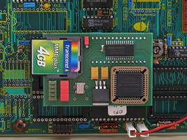
Ready.
1) Note that you need the 'GoMMC to Electron' interface (henceforth called 'the interface') to connect GoMMC to your Electron, and must run the 'Electron' version of the GoMMC software. The 'generic' GoMMC software will not work on an Electron, because some hardware locations are different.
2) Establish orientation on the interface. Looking at the side where the components are, with the Electron expansion port connector facing you, take note of 'north', 'south', 'east' and 'west' (e.g. the black, square chip with the red sticker on it is now 'east').
3) Note that the interface has two free IC sockets. The 32-pin (west) one is the 'utility' socket. The 28-pin (east) one is where you will install GoMMC.
4) Note the only jumper on the interface, just 'east' of the 28-pin socket. It is the ROM/SRAM jumper. It selects whether the utility socket contains a ROM or SRAM chip.
Then :
I.e. first you had something like this :

(a chip has been installed in the utility socket in this case), and after installing GoMMC, you have something like this :

The utility socket on the interface may remain empty. But it is meant to take a ROM or SRAM chip, providing up to 2 (for 28-pin chips) or 8 (for 32-pin chips) sideways ROM (if ROM) or RAM (if SRAM) banks. The chip must be suitable, e.g. it must have a standard JEDEC pinout, like a 27C1001 or 628128. If you put in a ROM, the ROM/SRAM jumper must be set 'west', else 'east'. If you put in a 28-pin chip, it must be 'lined up' to the south side of the 32-pin socket (i.e. the northmost 4 holes, 2 on each side, remain unoccupied). Before you actually put anything in the utility socket, refer to 'Sideways ROM/RAM' as well. If in doubt consult me first !
Now simply plug this 'combo' into your Electron's expansion port, at the back of the machine.
Ready.