TubeSilencer Guide
Use |
↖ |
TubeSilencer converts the signalling voltage of the Acorn Tube interface from the standard 5V to lower voltages (typically, 3.3V).
TubeSilencer has an 'in' and an 'out' connector. The 'in' connector is on the side marked '5V'. The 'out' connector is on the side marked 'LV'.
The 'in' connector connects TubeSilencer to your BBC's Tube connector, via a 'straight' (1:1) 40-wire flatcable (not supplied). When plugging in the cable, ensure that 'pin 1' matches on both sides. On the BBC side, pin 1 is clearly marked. On the TubeSilencer side, pin 1 is marked by a small triangle on the connector. Note that the orientation of the connector 'notch', relative to pin 1, is the same on both sides.
The 'out' connector connects TubeSilencer to your target hardware. It comes in two forms : 20-pin or 40-pin. The 40-pin connector has the same pinout as the 'in' connector, but has a few extra power pins (see below). The 20-pin connector is a 'condensed' version of the 40-pin one, and is designed to plug straight into some hardware development boards, like the Terasic DE0 Nano.
Note that, while all other signals are 'translated', nIRQ is simply passed from 'in' to 'out', because it's an 'open collector' a.k.a. 'open drain' signal (if active, it pulls the host IRQ 'low', and is tristated otherwise).
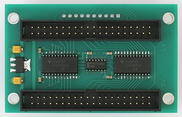
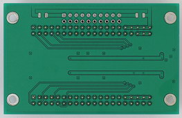
With a 40-pin 'out', your TubeSilencer will look like this (note that some details may differ) :
|
|
| Front | Back |
The connector pinout is :
| Description | Pin | Pin | Description |
|---|---|---|---|
| GND | 1 | 2 | RnW |
| GND | 3 | 4 | 2MHzE |
| GND | 5 | 6 | nIRQ |
| GND | 7 | 8 | nTUBE |
| GND | 9 | 10 | nRST |
| GND | 11 | 12 | D0 |
| GND | 13 | 14 | D1 |
| GND | 15 | 16 | D2 |
| GND | 17 | 18 | D3 |
| GND | 19 | 20 | D4 |
| GND | 21 | 22 | D5 |
| GND | 23 | 24 | D6 |
| GND | 25 | 26 | D7 |
| GND | 27 | 28 | A0 |
| GND | 29 | 30 | A1 |
| LV | 31 | 32 | A2 |
| LV | 33 | 34 | A3 |
| LV | 35 | 36 | 5V |
| LV | 37 | 38 | 5V |
| LV | 39 | 40 | 5V |
The pins marked 'LV' are power pins which are tied directly to the on-board regulator output (usually 3.3 V). Note that A4 through A6 (pins 36, 38 and 40) are not 'translated'. The corresponding 'in' pins are not connected, and the corresponding 'out' pins are tied directly to the BBC's 5V power supply. This means you can still use 5V if you need to.
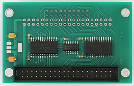
With a 20-pin 'out', your TubeSilencer will look like this (note that some details may differ) :
 |
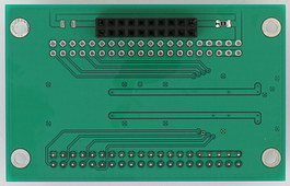 |
| Front | Back |
The connector pinout is :
| Description | Pin | Pin | Description |
|---|---|---|---|
| LV1 | 1 | 2 | GND |
| nRST | 3 | 4 | D0 |
| nTUBE | 5 | 6 | D1 |
| nIRQ | 7 | 8 | D2 |
| 2MHzE | 9 | 10 | D3 |
| RnW | 11 | 12 | D4 |
| A2 | 13 | 14 | D5 |
| A1 | 15 | 16 | D6 |
| A0 | 17 | 18 | D7 |
| LV2 | 19 | 20 | GND |
Normally, the pins marked 'LV1' and 'LV2' are not connected. However, if there is no on-board regulator, a 0 Ohm resistor (on the backside of the PCB) may be used to connect the pin, which should then provide the 'low voltage' power (usually 3.3 V) to TubeSilencer.