GoSDC-Atom Guide
Installation |
↖ |
1) Be aware of which GoSDC-Atom you have :
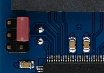
2) Take note of GoSDC's 6-pin configuration header (the one with the red jumper on it), in the following picture :

Its pins (in the orientation shown in the picture) are numbered :
| 5 | 6 |
| 3 | 4 |
| 1 | 2 |
So, in this example, there's a red jumper on 4+6 (note that your jumper may be a different colour). There's always a jumper on either 2+4 (selecting the secondary copy of the software) or 4+6 (selecting the primary copy of the software). The 'adapter', if installed (see below), connects to 3+5. (PRO differs)
3) Take note of the 'extra' that was supplied with your GoSDC : a 'socket-to-wire-to-jumper' adapter. (PRO differs)
1) Separate the two 'halves' of your Atom by removing the relevant screws.
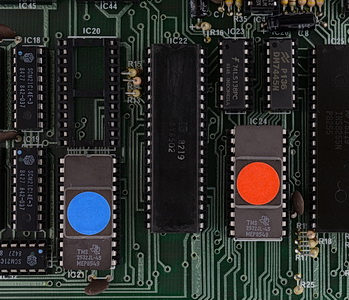
2) Looking at the PCB with the keyboard face down, take note of the IC sockets marked 'IC20', 'IC21', 'IC22' and 'IC24'.
3) About the 'socket-to-wire-to-jumper' adapter (henceforth called 'the adapter') that came with your GoSDC. Only with the adapter installed, GoSDC can act as the utility or extension ROM. (PRO differs)
4) Choose one of the following configuration options :
| Option | GoSDC version |
Adapter socket |
GoSDC can act as utility or extension ROM |
|---|---|---|---|
| A | OSR | - | Neither |
| B | OSR | IC24 | Utility ROM |
| C | OSR | IC21 | Extension ROM |
| D | PRO | n/a | Both |
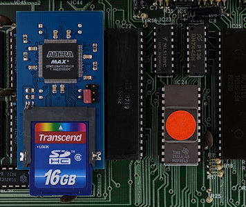
You should have (had) something resembling these pictures ('before' towards the left, 'after' towards the right) :
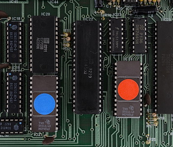
| → | 
| → | 
|
Ready.
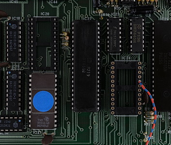
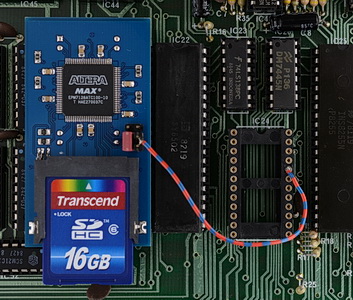
You should have (had) something resembling these pictures ('before' towards the left, 'after' towards the right) :
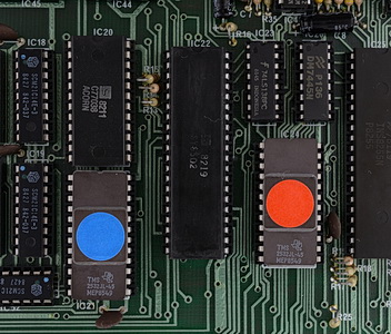
| → | 
| → | 
|
Ready.
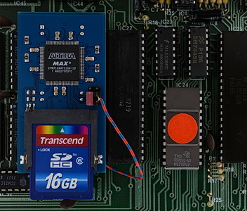
You should have (had) something resembling these pictures ('before' towards the left, 'after' towards the right) :
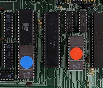
| → | 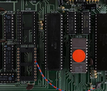
| → | 
|
Ready.
You should have (had) something resembling these pictures ('before' towards the left, 'after' towards the right) :

| → | 
| → | 
|
Ready.